|
|
|
Categories
|
|
Information
|
|
Featured Product
|
|
|
 |
|
|
There are currently no product reviews.
 ;
great manual readable & easy to downlaod to be recommanded
 ;
Very useful, not the best scan, but definitely readable !
;
Complete service manual, good quality scan, great buy !
;
Excellent manual, exactly what I needed! Fair price!
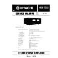
â� BLOCK DIAGRAM
ANT 8 8 0 -1 9 1 7 B A M /F M T U N E R O IC 3 0 2 LC 75386 E L E C T R O N IC VO LUM E IC 5 0 1 - 5 0 5 N JM 2060 E Q U A L IZ E R IC 5 0 6 TD A7560 P O W E R IC E N A
B L
FL SP+ RLSP+ FR SP+ RR FL RL FR RR F P SP SP SP SP SP +
P P -2 4 4 9 H -B :N O N F A D E R
G H C D C D M E C H A N IS M LPF IC 2 0 uPD RAD CON 178076G F IO /C D TR O LLER IC 9 0 1 LC 75853 L C D D R IV E R 1 POW ER SU PPLY
I K 1 2 J
TA2157F RF AMP
TC 94A14FA DSP KEY M A T R IX & S W IT C H
NC BA IL L IL L AC NC ON ON
CK UP .C O N T U M IN A T IO N C -S IG N A L IN -S IG N A L O U T
GND
M OTOR D R IV E R BA5983FP
LCD 6 4 5 7 LL+ R+ R-
â� ADJUSTMENT
Item Noise convergence Clock accuracy Procedure 1. Input a 98.1MHz/55dB(1kHz,30% MOD)signal.(0dB=1.4V) 2. Adjust the output to �18±3dB by VR102 when the SSG output is set �20dBμ. 1. Turn off and on the ACC switch,while holding CD EJECT button and POWER button.Repeat it twice slowly. 2. Set a universal timer to TP201,adjust TC201 so that a reading of the meter is 0±0.1 sec/day.
pin 28: NU pin 29: NU : - : Not in use. : - : Not in use. : - : Not in use. : - : Not in use. : - : Analog ground. : IN : Capacitor connection terminal to suppress the ripple. pin 34: VDD 0 pin 35: REG OSC pin 36: X 2 pin 37: X 1 pin 38: GND 0 pin 39: NU pin 40: GND 2 pin 41: AM IF pin 42: FM IF pin 43: VDD PLL pin 44: FM OSC pin 45: AM OSC pin 46: GND PLL pin 47: Voltage Tune pin 48: NU pin 49: IC pin 50: RESET_ pin 51: SP INIT pin 52: NU pin 53: ST_/TWEET_ pin 54: CLK INT pin 55: AUX ON_ pin 56: TEST pin 57: LCD ON_ : - : Positive supply voltage. : IN : Capacitor connection terminal to suppress the ripple. : - : Crystal connection. : - : Crystal connection. : - : Ground. : - : Not in use. : - : Ground. : IN : Input terminal counter for AM : IN : Input terminal counter for FM of the internal universal IF. of the internal universal IF.
Measuring instrument
SSG Milli-volt meter Universal timer
â� EXPLANATION OF IC
052-1173-00 uPD178076GF-541-3BA
1.Terminal Description pin 1: EJECT SW_ pin 2: NU pin pin pin pin pin pin 3: NU 4: VOL DATA 5: VOL CLOCK 6: VOL CE 7: NU 8: LCD DI_
Radio & CD Controller
pin 30: NU pin 31: NU pin 32: A VSS pin 33: REG CPU
: IN : The eject key signal input. : - : Not in use. : - : Not in use. : O : Serial data output to the electric volume IC. : O : Serial data clock output to the electric volume IC. : O : Chip enable signal output to the volume IC. : - : Not in use. : IN : Serial data input from the LCD driver. : O : Serial data output to the LCD driver. : O : Serial data clock output to LCD driver. : O : Chip enable signal output to the LCD driver. : - : Not in use.
pin 9: LCD DO pin 10: LCD CLK pin 11: LCD CE pin 12: NU
pin 13: POWER SW_ : IN : Power switch pulse input. pin 14: VOL 1 : IN : Volume control pulse input from the rotary switch. pin 15: VOL 2 pin 16: ILL_ pin 17: NU pin 18: NU pin 19: NU pin 20: NU pin 21: NU pin 22: NU pin 23: NU pin 24: NU pin 25: NU pin 26: NU pin 27: A VDD : IN : Volume control pulse input from the rotary switch. : IN : Illumination ON signal input. : - : Not in use. : - : Not in use. : - : Not in use. : - : Not in use. : - : Not in use. : - : Not in use. : - : Not in use. : - : Not in use. : - : Not in use. : - : Not in use. : - : Positive supply voltage for the Analog section.
: - : Positive supply voltage for the PLL. : IN : Input terminal of the internal counter for FM OSC( Local Oscillation ). : IN : Input terminal of the internal counter for AM OSC( Local Oscillation ). : - : Ground for the PLL. : O : PLL error output. : - : Not in use. : IN : Not in use. : IN : Reset signal input. : IN : 4SP = "L" , 2SP = "H". : - : Not in use. :I/O: Outputs "L" at AM 900kHz receiving. Inputs "L" at FM stereo receiving. : IN : Without the clock display = "H". : IN : AUX ON signal input. : IN : Test enable signal input. : O : LCD back light ON signal output.
-3-
PP-2449H
|
|
|
> |
|