|
|
|
Categories
|
|
Information
|
|
Featured Product
|
|
|
 |
|
|
There are currently no product reviews.
 ;
Very Good! All the diagram are easy to read, and its complete.
;
This was an excellent source of detailed assembly information on a device which is at least 12 years old. A very lucky find, coupled with great service.
;
Excellent Service Manual and best price on the Internet. This Service Manual covers everything you could ever need including full circuit schematics, component layout diagrams, stripdown procedure and full parts list/breakdown. I needed this to carry out a modification to one of these headunits and this manual covered everything I needed. Fast delivery, processed within a few hours.
 ;
Thought I would never find a copy of the Technics SX-EN2 Service Manual until I found Owner-Manuals.com. Price was very fair and I received the download promptly. While a photocopy, it is quite readable and includes all the pertinent information and diagrams. Thank you Owner-Manuals!
;
I really like this manual and it's reliable.I found and bought easly.thank you.
ADJUSTMENT
Item Clock accuracy
SUB
Procedure 1. Connect the Choronometer to TP218. 2. Connect the B/U and ACC line, and Turn on the ACC switch. 3. LCD display change Ver.---, While holding the buttons of MENU,M1,M5 and POWER. 4. Adjust TC201 so that an output of TP218 becomes 0.0 +0.2/-0.0Sec./day. 1. Input the 98.1MHz/55dBu(1kHz 22.5kHz Div.) SSG signal. 2. Set the output to 0dBm(1V)by main volume. 3. Adjust VR102 so that the output level is -18+3/-3dB down when the output of SSG is set to -20dBu. Connect the SSG to Main antenna (Red) side. Set the minimum VR101. Input the 98.1MHz/1kHz 22.5kHz(30%) Div. SSG signal. Input the 26dBu SSG signal and adjust VR101 so that an output of TP101(DIVADJ) becomes High from Low. 5. Confirm that TP101(DIV-ADJ) becomes Low from High within about three seconds of input the 22dBu SSG signal. 6. Confirm that TP101(DIV-ADJ) becomes 10.0V from 2.0V within about one second of input the 30dBu SSG signal. 7. Confirm that TP101(DIV-ADJ) is as follows 1.0V within five seconds of input the 20dBu SSG signal.
RR RH(+) RR RH(-) MUTE BACK UP RR LH(+) RR LH(-) FL FR LH(+) FR AM FR LH(-) RL
Measuring instrument
Choronometer
FM noise convergence
SSG Milli-volt meter
FM DIV.
1. 2. 3. 4.
FR RH(-) STBY
SSG Milli-volt meter Oscilloscope
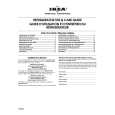
BLOCK DIAGRAM
Main section
J401(POWER/SP) ILLACC GND
IC402 POWER-IC TDA7560
FILLTER ILL CONT. Q415 BEEP Q414,416 Q410 CD-8V ACC-DET S615 CD-EJECT
ILL+
FR RH(+)
ILL
IC501 - 505 EQ-AMP NJM2060V
IC201 IC301 E-VOL LC75412 FM AUDIO-CPU LC723663 VR601 MAIN VOL.
CD
IC103 AM-NC BL101 AM/FM-TUNER AF-OUT OUT
Q408 CD-5V
S601 - 614 KEYMATRICS
IC601 LCD-DRIVER LC75853 1CD MECHANISM LCD601 DISP
ANT101 MAIN
IC102 AF-AMP IC101 FM-DIVER N-IN
SW PWB
PP-2898H-C,F
-4-
|
|
|
> |
|