|
|
|
Categories
|
|
Information
|
|
Featured Product
|
|
|
 |
|
|
There are currently no product reviews.
 ;
Delivery came quite promptly and in a very readable format. Thank you.
;
I found my Clarion VRX8370R in the Camper I bought and I wasn't able for month to understand it.
The Owner Manual was perfect and just what I was searching for.
Thank you.
Leonardo
;
Very good copy of Manual, clear and easy to print off, arrived very promptly and reasonably priced.
Thanks, I will use you again.
;
Zeer duidelijke afdrukken op A4-formaat , zeer uitgebreide handleiding . Pluspunt ,zeer snelle
respons van jullie , binnen de 24h . Top !!!
;
I AM HIGHLY IMPRESSED BY THE EASE OF USE OF THIS DOWNLOAD SERVICE. INSTRUCTIONS ARE CLEAR AND SIMPLE TO FOLLOW....EVEN BY TECHNOPHOBES SUCH AS MYSELF. THE EMAILS POINT YOU IN THE RIGHT DIRECTION...ITS SO EASY PEASY. THE DOWNLOAD CHOICE OF USER MANUALS IS EXTENSIVE AND I COULD NOT FIND A CHEAPER OR MORE EFFICIENT SERVICE ON THE INTERNET. I COULD NOT HAVE MADE A BETTER CHOICE OF INFORMATION PROVIDER. SHOULD I EVER NEED ANOTHER USER MANUAL, THEN THIS IS THE FIRST CHOICE SITE. COULD NOT BE BETTER PLEASED!!!!!!!...MANY THANXES FROM JIM BURNS
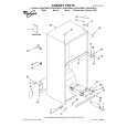
Main Cam Gear and Drive Rack Arm
Disassembly Procedure
1. 2. 3. 4. Remove the Main Cam Push Nut. (Refer to Note.) Pull up on the Main Cam Gear. Turn the Drive Rack Arm fully counterclockwise as shown. Pull up on the Drive Rack Arm.
Reassembly Notes
1. Alignment of Main Cam Gear and Drive Rack Arm 1) Install the Drive Rack Arm so that the hole (A) is aligned with the hole on chassis as shown (Through hole (A)). 2) Install the Main Cam Gear so that the 2 holes (B) marked "E" are aligned with the hole on chassis as shown (Through hole (B)). ("E" indicates the EJECT position.)
Chassis Hole 7 Main Cam Gear 8 Drive Rack Arm turn Main Cam Gear Chassis Hole
E
mark Chassis Through Holes (B)
Drive Rack Arm Through Hole (A)
Fig. J5-3
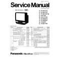
Main Cam Push Nut
Fig. J5-1 Note: When removing the Main Cam Push Nut, use a screwdriver etc. Shaft of Main Cam Gear Main Cam Push Nut Bottom of Chassis
2. Installation of Main Cam Gear and Main Cam Push Nut 1) Position the chassis upside down placing a Support under the Main Cam Gear. Install the Main Cam Push Nut with Needlenose Pliers etc. so that it is flush with the chassis. There may be some slight scratches on the Shaft of Main Cam Gear, when removing the Main Cam Gear. In case that the Main Cam Gear can be installed securely without tottering, it is fine to use the one. If any tottering, replace a new one.
Press Needlenose Pliers Shaft of Main Cam Gear
Screwdriver
Bottom of Chassis
Main Cam Push Nut Main Cam Gear
Main Cam Gear support Fig. J5-2 Fig. J5-4 3. Main Cam Push Nut is not reusable. If removed, install a new one.
2-10
|
|
|
> |
|