|
There are currently no product reviews.
 ;
hat alles sehr gut geklappt. Das Servicemaual ist gut zu verwenden. Die Pläne und Schrift
ist klar und leserlich. Außerdem preiswert. Grüße an alle Hifi-Bastler
;
I got the manual quickly after the payment was transfered (1 day). The manual was exactly what i needed and the updates via e-mail were great. Thanx!
;
I've looked for this manual all over that internet, you guys had it and to a good price. A++++
;
I've looked some time for this manual, you guys had it and to a good price. A++++
 ;
factory technician level - complete with board views :
( removing chassis from cabinet , only thing missing ) ;
on weekends , staff is not available so - be patient .
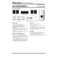
Front
Surround
Subwoofer
Center
RRV3590
S-FCRW2900-S
ORDER NO.
SPEAKER SYSTEM
S-FCRW2900-S
XJC/E
1. REASSEMBLY AND DISASSEMBLY PRECAUTIONS
1.1 FRONT/SURROUND SPEAKER
The grille is attached to the cabinet by 6 external screws. To detach it, unfasten those screws. The speaker unit, together with the grille, is attached to the cabinet by 4 external screws. To detach it, first unfasten those screws. Next remove the cabinet. Then removethe cable. When attaching it, face its terminal downward.
1.3 SUBWOOFER
The speaker unit is attached to the back board by 4 external screws. To detach it, unfasten those screws. When attaching it, face its terminal downward. The cosmetic baffle assy is attached to the baffle board by press-fitting. To detach it, pry it open by inserting a flat blade screwdriver into lower slot.
1.2 CENTER SPEAKER
The grille assy is attached to the cabinet by 8 external screws. To detach it, unfasten those screws. The speaker unit, together with the grille assy, is attached to the cabinet by 4 external screws. To detach it, first remove the grille assy. Next remove the cabinet. Then removethe cable. When attaching it, face its terminal toward the input terminal.
PIONEER CORPORATION
4-1, Meguro 1-chome, Meguro-ku, Tokyo 153-8654, Japan PIONEER ELECTRONICS (USA) INC. P.O. Box 1760, Long Beach, CA 90801-1760, U.S.A. PIONEER EUROPE NV Haven 1087, Keetberglaan 1, 9120 Melsele, Belgium PIONEER ELECTRONICS ASIACENTRE PTE. LTD. 253 Alexandra Road, #04-01, Singapore 159936
PIONEER CORPORATION 2007
T-ZZR MAY 2007 Printed in Japan
|