|
|
|
Categories
|
|
Information
|
|
Featured Product
|
|
|
 |
|
|
There are currently no product reviews.
 ;
Perfect source for service manuals: fast and professional transaction; high quality, perfect readable and largely scaleable PDF; complete schemes, diagrams and spare part list. Tnx a lot, cu again!!!!
;
I got your link from a friend and I must say that I am really satisfied with your service. Specially this B&O manual I didn't find anywhere on the web... but you could deliver it :-) . You deliver very fast and the copy is of good quality. So your webpage is bookmarked. Thanks
;
This was the Sony CCU-500A Service manual I was looking for.
The price was reasonable.
The permission to download was quck.
I will use Owner-Manual.com for all my manual needs.
;
Excellent printing quality.
A complete and very usefull service manual with all details.
GREAT SERVICE AT VERY LOW PRICE!
A+++++++++++++++++++++++++
;
Excellent printing quality.
A complete and very usefull service manual with all details.
GREAT SERVICE AT VERY LOW PRICE!
A+++++++++++++++++++++++++
1
2
3
4
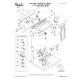
SH-D09
A
DESCRIPTION OF SCHEMATIC DIAGRAM
VOLTAGE MEASUREMENT CONDITION:
1. Voltages at test points are measured at the supply voltage of AC 120V. Signals are fed by a color bar signal generator for servicing purpose and the above voltages are measured with a 20k ohm/V tester. CAUTION:
This circuit diagram is original one, therefore there may be a slight difference from yours.
SAFETY NOTES:
1. DISCONNECT THE AC PLUG FROM THE AC OUTLET BEFORE REPLACEING PARTS. 2. SEMICONDUCTOR HEAT SINKS SHOULD BE REGARDED AS POTENTIAL SHOCK HAZARDS WHEN THE CHASSIS IS OPERATING.
WAVEFORM MEASUREMENT CONDITION:
1. Waveforms at test points are observed at the supply voltage of AC 120V. Signals are fed by a color bar signal generator for servicing purpose.
IMPORTANT SAFETY NOTICE:
PARTS MARKED WITH � � ( ) ARE IMPORTANT FOR MAINTAINING THE SAFETY OF THE SET. BE SURE TO REPLACE THESE PARTS WITH SPECIFIED ONES FOR MAINTAINING THE SAFETY AND PERFORMANCE OF THE SET.
B
INDICATION OF RESISTOR & CAPACITOR:
RESISTOR 1. The unit of resistance ��� is omitted. (K=k�=1000 �, M=M�). 2. All resistors are ± 5%, unless otherwise noted. (J= ± 5%, F= ± 1%, D= ± 0.5%) 3. All resistors are 1/16W, unless otherwise noted. CAPACITOR 1. All capacitors are µF, unless otherwise noted. (P=pF=µµF).
C
D
20
1 2 3 4
|
|
|
> |
|