|
|
|
Categories
|
|
Information
|
|
Featured Product
|
|
|
 |
|
|
There are currently no product reviews.
 ;
Last week I bought a second hand BAUKNECHT TRK4850 DRYER. It is a professional machine with many programs and switch options. I feared it would be a huge quest to find a manual. I was delighted when I found owner-manuals.com. After payment I received the file to download the next day already. The quality is great. I am very happy. Thanks!
but kindly the distributions of the operating programs not find in the owners manual,can you help me to understand the operating programs instructions thank you
;
Very good copy, very readable and easy transaction as always.
;
It is perfect, exactly what we needed. It's like the paper version but less clutter.
 ;
Received my manual within 24 hours. Very clear scan of the manual I needed. Thanks!
;
Very clear scan, I recommend it. Definitely a must have for any 3362 owner.
Alpine could have written a slightly more complete manual, though. It's already pretty huge, but the unit has so many functions, I feel some more explanation would have been better.
Yamaha's manual of their comparable YDSP-1 is a little better in my opinion.
2.
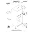
HOW TO REPLACE A ROTARY UPPER DRUM (777HF, 778HFMODEL)
See below for note.
2-1.
1) 2) 3)
HOW TO REMOVE A ROTARY UPPER DRUM
2-2.
1) 2)
Remove screw 1 (+P3 � 8) and remove the ground shaft assembly 2. (Refer to Fig. 4.) Remove soldering which is marked by arrow and remove the rotary upper drum board completely. Remove two screws 3 (PSW3 � 8) and remove the rotary upper drum in the direction of A. (Refer to Fig. 5.) If removal is difficult, remove it while rotating it slowly.
HOW TO ATTACH A NEW ROTARY UPPER DRUM
3)
Pay attention so that finger print or like must not be put when inserting a new upper drum into lower drum. Align mark of the rotary upper drum board with the mark of the rotary transformer board so that the screw hole on the upper drum and that on the lower drum are aligned. (Refer to Fig. 5.) If attaching is difficult, attach a upper drum while rotating it slowly.
Note: If removal is difficult, check again if soldering is removed completely.
2 Ground shaft assembly 1 Screw (+P3 � 8)
Note: Pay attention not to damage the video heads. Confirm that the upper drum is inserted completely. 4) 5) Tighten the two screws 3 (PSW3 � 8). (Refer to Fig. 5.) Fix the earth shaft 2 by tightening the screw 1 (+P3 � 8) so that protrusion at the tip of the earth shaft contacts the center of the drum shaft.
Soldering Soldering
4 Plate spring
Drum when viewed from the top
Note: When attaching the ground shaft assembly 2, never give force to the plate spring 4.
3 PSW3 � 8
Upper drum assembly DZR-45-R (8-848-576-02) (777HF, 778HF)
A
Align the two arrow marks.
Fig. 4
Lower drum assembly DZL-51B/J-RP (8-848-666-11) (777HF, 778HF)
Fig. 5
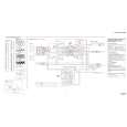
NOTE : There are two types of drum assembly built in models except SLV-788HF (DZH-94A/Z-RP only). [Discrimination]
UPPER DRUM ASSEMBLY DZR-45-R (777HF, 778HF) (8-848-576-02)
DRUM ASSEMBLY DZH-94A/Z-RP (8-839-044-02)
�Top View�
�Top View�
There are two printed circuit boards on the top.
There is no printed circuit board.
Note: It cannot be divided to two parts, the upper and the lower drum assemblies.
�7�
|
|
|
> |
|