|
|
|
Categories
|
|
Information
|
|
Featured Product
|
|
|
 |
|
|
There are currently no product reviews.
 ;
This is the original manufacturers service manual, with detailed info on the circit boards, explosion drawings of all parts in assembly order, and tuning instructions. The only thing missing is the information on the dimensions of the various drive belts. mail me if you need them. gcrossman_at_aol.com
;
Ordered service manuel for a hard to find plasma tv - your company made it easy to find and purchase - I will use you again
Thanks for your help
 ;
This is a high quality manual with clear schematic and components layout diagrams ; with service procedure included.
;
This service manual for the Kenwood KT-990D was reproduced really well ,is very legible and manual is complete.Combined with the low price paid,in the future,I will be checking Owner-Manuals.com any time I need a manual.
;
When I purchased this manual I had my doubts regarding the quality as the price was so reasonable as compared to other outlets.
The manual itself is of high standard the print is very clear as are the diagrams. Obviously with the diagrams one has to zoom in otherwise it is to small to be able to read.
Overall I am very pleased with the company who delivered as they said and with the manual they supplied.
I occasionally require a manual and now having registered with this company I shall order from them in the future.
2.
HOW TO REPLACE A ROTARY UPPER DRUM (777HF, 778HFMODEL)
See below for note.
2-1.
1) 2) 3)
HOW TO REMOVE A ROTARY UPPER DRUM
2-2.
1) 2)
Remove screw 1 (+P3 � 8) and remove the ground shaft assembly 2. (Refer to Fig. 4.) Remove soldering which is marked by arrow and remove the rotary upper drum board completely. Remove two screws 3 (PSW3 � 8) and remove the rotary upper drum in the direction of A. (Refer to Fig. 5.) If removal is difficult, remove it while rotating it slowly.
HOW TO ATTACH A NEW ROTARY UPPER DRUM
3)
Pay attention so that finger print or like must not be put when inserting a new upper drum into lower drum. Align mark of the rotary upper drum board with the mark of the rotary transformer board so that the screw hole on the upper drum and that on the lower drum are aligned. (Refer to Fig. 5.) If attaching is difficult, attach a upper drum while rotating it slowly.
Note: If removal is difficult, check again if soldering is removed completely.
2 Ground shaft assembly 1 Screw (+P3 � 8)
Note: Pay attention not to damage the video heads. Confirm that the upper drum is inserted completely. 4) 5) Tighten the two screws 3 (PSW3 � 8). (Refer to Fig. 5.) Fix the earth shaft 2 by tightening the screw 1 (+P3 � 8) so that protrusion at the tip of the earth shaft contacts the center of the drum shaft.
Soldering Soldering
4 Plate spring
Drum when viewed from the top
Note: When attaching the ground shaft assembly 2, never give force to the plate spring 4.
3 PSW3 � 8
Upper drum assembly DZR-45-R (8-848-576-02) (777HF, 778HF)
A
Align the two arrow marks.
Fig. 4
Lower drum assembly DZL-51B/J-RP (8-848-666-11) (777HF, 778HF)
Fig. 5
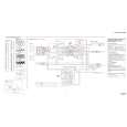
NOTE : There are two types of drum assembly built in models except SLV-788HF (DZH-94A/Z-RP only). [Discrimination]
UPPER DRUM ASSEMBLY DZR-45-R (777HF, 778HF) (8-848-576-02)
DRUM ASSEMBLY DZH-94A/Z-RP (8-839-044-02)
�Top View�
�Top View�
There are two printed circuit boards on the top.
There is no printed circuit board.
Note: It cannot be divided to two parts, the upper and the lower drum assemblies.
�7�
|
|
|
> |
|