|
|
|
Categories
|
|
Information
|
|
Featured Product
|
|
|
 |
|
|
There are currently no product reviews.
 ;
El producto satisface las necesidades del servicio t
;
This is a good quality scan of the Operation & Maintenance (Service) Manual for the PAL version of this high-band broadcast umatic, BVU-800P
All schematics and lineup procedures appear to be included in this one manual AFAICT.
The file size is just over 113 MB which gives an idea of the quality and number of pages.
All of the schematics, which contain some fairly small print, are easily readable when you zoom into the page.
John Thompson, Newcastle Upon Tyne, England.
;
Good quality, all schematics of few of models. There is also short form of user manual and regulation manual.
;
Perfect copy of the service manual. you can enlarge every page, and it comes up
with all details.
;
It´s very very nice manual with all, what i need. Original in good quality. Very fast business. Very much thanks...
SECTION 6 ADJUSTMENTS
6-1 MECHANICAL ADJUSTMENTS
For the mechanical adjustments, please refer to the �VHS MECHANICAL ADJUSTMENT MANUAL (S MECHANISM)� (9-921-647-11).
SLV-AX10/AX20/N50/N60/N70/N80/ LX4/LX5/LX6S/LX7S/LX8S
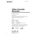
2-1-3. Set-up of Adjustment In this adjustment, NTSC pattern generator is connected with LINE input terminal. When check to tuner, connected AERIAL terminal. Check that the synchronizing signal of the Y signal has an amplitude of approximately 0.7 V and that the burst signal has an amplitude of approximately 0.3 V and its waveform is flat. And check that the level ratio of burst signal to �red� signal is 0.30 : 0.66. The video signal (color bar) used for electrical aligning this unit is shown in Fig. 6-2-2.
6-2. ELECTRICAL ADJUSTMENTS
See the adjusting part location diagram from on page 6-6 for the adjustment. 2-1. PREPARATION BEFORE ADJUSTMENT 2-1-1. Equipment Required The measuring instruments used for this alignment include: 1) Monitor TV 2) Oscilloscope, dual-trace, bandwidth of 30 MHz or more, with delay mode (A probe 10:1 should be used unless otherwise specified.) 3) Frequency counter 4) NTSC Pattern generator 5) 6) 7) 8) 9) 10) Remote commander Digital voltmeter Audio generator Audio level meter Audio attenuator Alignment tapes KRV-51N2 (NTSC) Part No. : 8-192-605-32
NTSC model
White (100%)
About 0.7 V About 0.3 V Red Horizontal sync signal Burst signal (It must be flat.)
About 0.3 V
Fig. 6-2-2 Color Bar Signals of Pattern Generator
2-1-4. Alignment Tape � Contents of KRV-51N2 Audio signal Mode Period 7 minutes 3 minutes 7 minutes 3 minutes Video signal Color bar Monoscope Color bar Monoscope Hi-Fi 400Hz (L/R) Normal 400Hz 1 2 3 4
2-1-2. Equipment Connection Unless otherwise specified, connect and adjust the measuring instruments as shown in the following diagram.
VIDEO LINE IN Pattern generator VCR Monitor TV
SP LP
Video output (75�)
VIDEO LINE OUT
Fig. 6-2-1
6-1
 $4.99 SLVN70 SONY
Owner's Manual Complete owner's manual in digital format. The manual will be available for download as PDF file aft…
|
|
|
> |
|