|
|
|
Categories
|
|
Information
|
|
Featured Product
|
|
|
 |
|
|
There are currently no product reviews.
 ;
We received the manual in a timely manner and it was exactly what we were expecting. Excellent replacement for original Service Manual.
All schematics are very legible. We are really satisfied.
;
We received the manual in a timely manner and it was exactly what we were expecting. Excellent replacement for original Service Manual.
All schematics are very legible. We are really satisfied.
;
We received the manual in a timely manner and it was exactly what we were expecting. Excellent replacement for original Service Manual.
All schematics are very legible. We are really satisfied.
;
We received the manual in a timely manner and it was exactly what we were expecting. Excellent replacement for original Service Manual.
All schematics are very legible. We are really satisfied.
;
We received the manual in a timely manner and it was exactly what we were expecting. Excellent replacement for original Service Manual.
All schematics are very legible. We are really satisfied.
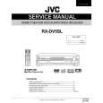
CX68K5 SX68K7
CONVERGENT VIDEO LEVEL ADJUSTMENT CHECKING
NO POINT ADJUSTMENT CONDITION / PROCEDURE WAVEFORM OR OTHERS VIDEO DET B/G -PAL Color bar (100% white bar) is 1 CONVERGENCE (1) Receive the "Crosshatch Pattern" signal. B G R
G
LEVEL received ADJUSTMENT (2) Using the remote controller, call NORMAL ADJUSTMENT (2) Adust R476 to make video output of the (To be done after mode. B R476 AV-OUT terminal become 1.0 ± 0.05 Vp-p at the purity R
the 75� terminator. adjustment.)
(Static convergence) (1) Turn the 4 pole magnet to a proper opening angle in order to superpose the blue and red
R G B colours.
Fig. a
(2) Turn the 6 pole magnet to a proper opening angle in order to superpose the green colour G over the blue and red colours. B
R
B
(Dynamic convergence) Fig. b (1) Adjust convergence on fringes of the R G B screen in the following steps. G a) Fig. a: R Drive wedge at point "a" and swing the
PURITY ADJUSTMENT
NO POINT ADJUSTMENT CONDITION / PROCEDURE WAVEFORM OR OTHERS deflection coil upward. 1 PURITY
a b
ADJUSTMENT beam current to 1,400µA Drive the wedge at point "b" "c" and B G R R
c b) Fig. b: (1) Receive GREEN -ONLY signal. Adjust the
(2) Degauss CRT enough with the degausing G
swing the deflection coil downward.
coil. c) Fig. c: B NOTE: Follow the Job Instruction Sheet to Drive "c" wedge deeper and swing the 90mm 1-1 d) d: Fig. d Vertical Bv: Refer to the factory
adjust the magnetic field. deflection coil rightward.
A tape over them. magnetic field and keep the static
(2) Fix all wedges on the CRT and apply glass (3) Maintain purity magnet at the zero screw, magnet unit (purity, 4 pole, 6 pole
A=B (3) Apply lacquer to the deflection yoke lock convergence roughly adjusted.
Drive "b" wedge deeper and swing the Horizontal Bh: setting page. (Reference: page 11)
Wedge "a" deflection coil leftward.
8
will change to RGB mono colour mode. GREEN BLUE RED
About
100 Deg. (4) Observe the points a, b, as shown in Fig.1 1 100 Deg.
B About
Lacquer
Fig. 1-2 Rank A (On the right of CRT)
Wedge "b"
through microscope. Adjust the landings to magnets) and magnet unit lock screw. Finally received the Red and Blue only A rank requirement. signals to make sure there is no other colours (5) Orient the raster rotation to 0 eastward. on the screen. (6) Tighten up the deflection coil screws.
6-Pole Magnet. CRT NECK
Wedge "c"
Tightening torque : 108N 20N (11Kgf ± 2Kgf)
A
(7) Make sure CRT corners landing meet the
A rank requirements. If not, stick the magnet A=B sheet to correct it. B Note : This adjustment must be done after
26mm ± 0.5mm warming up the unit for 30 minutes or
Fig. 1-3 Rank A (On the left of CRT) longer with a beam current over Lacquer Purity Magnet 1,400µA. 4-Pole Magnet
*For the following colours press to *Press R/C RGB key for 1 second change. in NORMAL MODE, the colour
ONLY
Signal-colour
8-1 8-2
|
|
|
> |
|