|
|
|
Categories
|
|
Information
|
|
Featured Product
|
|
|
 |
|
|
There are currently no product reviews.
 ;
complete part-lists and pcb layout, schematic diagram is good enlargable,
;
Excellent, fast delivery, excellent product. Good luck!
;
This manual is for the usa model only. But it is clear
, accurate and comprehensive, including board layouts and schematics.
I found it extremely useful for my mitsubishi dp-86da, but the same diagram would also work for the realistic lab5000 and hi fi 80. Thanks.
;
Great to have extra resources for Service Manuals, Now days you can really not trouble shoot efficiently without one , Wayne at IRIONS TV & ELECTRONICS REPAIR Clearwater , Fl. 33755 727-446-7955
 ;
For five bucks you can barely buy a hamburger. Or for the same five bucks you can buy a service manual. Much more useful. (and better for your health, depending on where you buy your hamburgers).
Yes, there are free manual sites out there, but if they don't have what you want, you have to pay.
And five bucks isn't much. Not for full specs, schematics and adjustment and parts replacement procedures.
My only criticism is that grayscale illustrations aren't well rendered, but I've seen worse.
Schematics and text are clear.
I'll be happy to purchase from here again.
Mike
[email protected]
TC-WE675
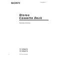
Record/Playback Head Azimuth Adjustment DECK A Procedure: 1. Forward Playback Mode
test tape P-4-A100 (10 kHz, �10 dB) 47 k� set level meter
DECK B
Tape speed Adjustment Adjust DECK A first Procedure: � Forward Playback Mode �
test tape WS-48B (3 kHz, 0 dB)
DECK A
DECK B
frequency counter 47 k� set
LINE OUT
LINE OUT
2. Turn the adjustment screw for the maximum output levels. If these levels do not match, turn the adjustment screw until both of output levels match together within 1 dB.
L-CH peak
output within 1 dB level
within 1 dB
screw position
R-CH peak L-CH peak R-CH peak
screw position
3. Playback Mode
test tape P-4-A100 (10 kHz, �10 dB) L-CH 47 k�
(High speed adjustment) 1. Press the PITCH CONTROL button to set to OFF . 2. Set to test mode. (Refer to page 11.) 3. Press the H button to playback. 4. Press the HIGH/NORMAL button to playback at double speed. 5. Adjust RV316 (DECK A), RV416 (DECK B) so that the frequency counter reading becomes 5,980 ± 80 Hz. (Normal speed adjustment) 6. Press the H button to playback. 7. Press the HIGH/NORMAL button to playback at normal speed. 8. Adjust RV317 (DECK A), RV417 (DECK B) so that the frequency counter reading becomes 3,000 ± 90 Hz. (Pitch control adjustment) (DECK A) 9. Press the PITCH CONTROL button to set to ON . 10. Set PITCH CONTROL knob to mechanical center. 11. Press the H button to playback. 12. Adjust RV318 so that the frequency counter reading becomes 2,990 ± 90 Hz. Adjustment Location: MAIN board (See page 14.)
oscilloscope
set
V
H
Sample value of wow and flutter W.RMS (JIS) less than 0.3% . (test tape : WS-48B) Playback Level Adjustment Procedure: � Forward Playback Mode �
test tape P-4-L300 (315 Hz, 0 dB) 47 k�
DECK A
DECK B
R-CH
47 k� LINE OUT Screen Pattern
level meter
In phase
45� good
90�
135�
180�
set
wrong
LINE OUT
4. Change the reverse playback mode and repeat the steps 1 to 3. 5. After the adjustment, lock the adjustment screws with suitable locking compound. Adjustment Location: � record/playback head �
Adjust DECK A : RV111 (L-CH), RV211 (R-CH) and DECK B : RV121 (L-CH), RV221 (R-CH) so the level meter reading becomes the adjustment limits below. Adjustment Value: LINE OUT level : �7.7 dBs ± 0.5 dB (0.301 to 0.338 V) Level difference between channels : within 0.5 dB Confirm that the LINE OUT level does not change in playback mode while changing the mode from playback to stop several times.
reverse side
forward side
Adjustment Location: MAIN board (See page 14.)
adjustment screws
9
|
|
|
> |
|