|
|
|
Categories
|
|
Information
|
|
Featured Product
|
|
|
 |
|
|
There are currently no product reviews.
 ;
We received the manual in a timely manner and it was exactly what we were expecting. Excellent replacement for original Service Manual.
All schematics are very legible. We are really satisfied.
;
Fast delivery and good quality manual.
Very easily downloadable from a given url.
Will be pleased to buy again from this seller.
;
Ottimo manuale, grafica ferfetta invio rapidissimo. Altissimo livello!!!!!
;
Great PDF easy to read good info needed for replacment of belts and assembly and specs.
;
complete and unabridged very good quality
easy to download.
recieved in two days.
Level 3 Service Manual COSMO
3.c.1
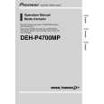
Reception Block Diagram.
Mecha
GSM SUPPLY
SW
FL 504
TR504
FL 503
FL 500
FILTER
45 MHz
225 MHz GSM RX : 925 � 960 MHz
45 MHz
SW700
270 MHz
DCS RX : 1805 - 1880 MHz DCS SUPPLY
TR503 LNA
FL 502
FL 501
1/2
GSM & DCS :1080 MHz GSM & DCS : 540 MHz
1/2
RX I,Q
CLK SDATA SLE
IF PLL
1/2
IC602
1/2 90 MHz
DEMOD
RF PLL
RX GSM : 1150 - 1185 MHz RX DCS : 1580 � 1655MHz
TCXO 13 MHz
Description of Reception Block Diagram.
E-GSM band (925-960 MHz). Incoming RF signal from aerial is filtered and switched to the RX GSM path through SW700 . The signal is filtered by FL504 , before being amplified by TR504 , and is further filtered by FL503. Then, the signal input sent to RF-IC (IC600) in a first mixer stage. The RF signal (925-960 MHz) is mixed with the RF-PLL Frequency (1150-1185 MHz) coming from IC601 (PLLs & VCOs). For the channel 1, the output signal of the mixer is 225 MHz (1150 - 925 = 225 MHz), and is filtered by FL500. DCS band (1805-1880 MHz). Incoming RF signal from aerial is filtered and is switched to the RX DCS path through SW700 . The signal is filtered by FL501 , before being amplified by TR503 , and is further filtered by FL502. Then, the signal input to RF-IC (IC600) in a first mixer stage. The RF signal (1805-1880 MHz) is mixed with the RF-PLL Frequency (1580-1655 MHz) coming from IC601 (PLLs & VCOs) via IC602 (RF-VCO). For the channel 1, the output signal of the mixer is 225 MHz (1805 Mhz-1575 MHz = 225 MHz), and is filtered by FL500. For the E-GSM and DCS bands. The first intermediate frequency is 225 MHz. Then, this frequency is filtered by FL 500 before input to the second mixer stage. The first IF (225 MHz) is mixed with the 270 MHz (Fixed Frequency PLL 540 /2 = 270 MHz), to a second IF 45 MHz. The second IF is demodulated to Base Band (IC300) I/Q phase demodulated signals. RF-IC (IC600) provides automatic gain control. IC600 includes a quadrature demodulator. The second IF signal (45 MHz) is demodulated to I, Q balanced signals for One-C.
Version A Date: 04/00
12/29
Mitsubishi Electric Telecom Europe S.A. ZA le Piquet 35370 Etrelles Phone: +33 2 99 75 71 00 Fax: + 33 2 99 75 71 47
|
|
|
> |
|