|
|
|
Categories
|
|
Information
|
|
Featured Product
|
|
|
 |
|
|
There are currently no product reviews.
 ;
Perfect manual, perfect service. Easy reading. Thanks a lot
;
Very good quality download here. Great hard to find manuals at a reasonable price.
 ;
I had a problem with the mains transformer, I did not know the voltages on the secondary, this manual helped me to solve this problem, thanks for the manual!
;
Great manual, great quality copy, complete parts reference and scematics, Thank you
;
Very good as always. Also this manual appears clear and well processed. I know it will help me to work on this TV. Thank you a lot! Matteo
TX-DS898
A
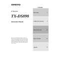
Idling current adjustment Before Idling adjustment, turn the trimming resistors R6040 to R6046 to counter clockwise. Connect the DC voltmeter to sockets P6080 to P6086. After turn POWER to ON, adjust the trimming resistors R6040, R6041 and R6042 so that the reading of voltmeter becomes 7.0 mV. (Front and center channels) Adjust the trimming resistors R6043, R6044, R6045 and R6046 so that the reading of voltmeter becomes 5.0 mV. (Surround and surround back channels) After adjustment, attach the top cover. Confirm the voltage of points above after about five minutes. Front and center channels When less than 9.0 mV, readjust the resistors above so that the voltage becomes 9.0 mV. When 9.0 mV to 11.0 mV, you are not necessary to adjust. When more than 11.0 mV, readjust the resistors above so that the voltage becomes 11.0 mV. Surround and surround back channels When less than 6.0 mV, readjust the resistors above so that the voltage becomes 6.0 mV. When 6.0 mV to 8.0 mV, you are not necessary to adjust. When more than 8.0 mV, readjust the resistors above so that the voltage becomes 8.0 mV. Note: No load and No signal
B
C
D
ADJUSTMENT AND CONFIRMATION PROCEDURES
1
2
L ch.
DI-
R ch.
DI-
C ch.
DI-
3
P6083
+ID -ID
R6040
P6080
R6041
P6081
R6042
P6082
R6043
P6084
+ID -ID
R6044
P6085
+ID -ID
R6045
P6086
+ID -ID
R6046
SL ch.
SR ch.
SBL ch.
SBR ch. NAAF-7250
4
Confirmation of protection circuit 1. Confirmation of operation of speaker relay Confirm that the speaker relays turn ON approximate. 5 seconds after the power switch is turned ON. Confirm that the speaker relays turn OFF immediately after the power switch is turned OFF. 2. Confirmation of DC detection circuit Press and hold down CD button, then press STANDBY/ON and DISPLAY buttons to set the unit to "TEST-1" mode. After "TEST-1" on the FL tube light on, press VIDEO 1 button to set the unit to "TEST-1-00". Apply DC 1.5 to 3V to MULTI CHANNEL INPUT terminal with no load. Confirm that the speaker relay turns OFF. Apply DC -1.5 to -3V to MULTI CHANNEL INPUT terminal with no load. Confirm that the speaker relay turns OFF. Caution: Don't apply DC voltage more than 1 sec..
5
DI+
DI+
DI+
|
|
|
> |
|