|
|
|
Categories
|
|
Information
|
|
Featured Product
|
|
|
 |
|
|
There are currently no product reviews.
 ;
This service is relatively cheap, document is fast available, schematic is readable.
Thanks.
 ;
So far I´m a satisfied customer. I have only downloaded "TECHNICS SX-KN470 Service Manual" maybe I will use it later.
Best regards
Peter
;
Good manual. It is complete and of high quality, both text and graphics. The schematics are with the original big size, so it can be viewed or printed without any loss of resulution and sharpness.
;
We needed a manual quickly...online it was available immediately, at a very low price. We loved the convenience!
;
Excellent!!
Got what I need and very fast!!
Thank You
UX-M5
Cassette amplifier section
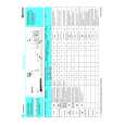
Item Head azimuth adjustment Measuring condition Test tape: VT702 (8kHz) Signal output terminal: PHONES (with 32 ohm load) Check and adjustment procedure 1.Play back the test tape VT702 (8kHz). 2.Adjust the head azimuth adjusting screw so that the Standard value Output level: Within (0+2dB-2dB) Adjusting part Head azimuth adjusting screw (To be used only after head replacement) See Fig.1 on page 1-16.
phase difference between the R and L channels is of maximum output minimized at an output level that is within (0+2dB-2dB) level of the maximum output level. After this adjustment, Phase difference R lock the head azimuth adjusting screw with screw sealant to cover more than a half of the screw head. 3.When the head azimuth is maladjusted, correct it with the head azimuth adjusting screw. and L channels: Minimum
Tape speed and wow/flutter check and adjustment
Test tape: VT712 (3kHz)
1.Play back the test tape VT712 (3kHz) by the end portion.
Tape speed: Motor semifixed resistor
Signal output terminal: 2.Connect a frequency counter and check that it reads 2940 to 3090Hz PHONES between 2940 and 3090Hz. If not, adjust the frequency (with 32 ohm load) with the motor semifixed resistor. 3.Check that the wow/flutter is within 0.38% (unweighted). Within 0.38% (unweighted) Deviation between 1kHz and 8kHz: (0+3dB-6dB)
See Fig.2 on page 1-16. Check only
PB frequency response check
Bias frequency check
Test tape: VT702 Signal output terminal: PHONES (with 32 ohm load) Tape: Normal Signal output terminal: Cassette REC./PLAY HEAD Test tape: AC225 Signal input: FM 22.5 DEV 60dBu with emphasis Signal output terminal: PHONES (with 32 ohm load)
Play back the test tape VT702 while con-firming that deviation between the 1kHz signal and 8kHz signal should be (0+3dB-6dB). Set the TUNER or CD function and with TAPE to record. Check to see if the frequency at the measuring point P201 is (67kHz+1kHz-1kHz) if not adjust L203 until the frequency counter indicates (67kHz+1kHz -1kHz). At TUNER, set the BAND to the FM position, and record the reference 1kHz signal and 8kHz signal alternately repeatedly. While playing back the recorded signal differ from that of the 1kHz signal by within (0+3dB-6dB).
L203, P201 See Fig.3 on page 1-16.
REC and PB frequency response adjustment
Level difference between REC and PB: Within (0+3dB-6dB)
Tuner section
Item AM IF adjustment Measuring condition Signal input: Loop antenna Signal output: IC101 pin19 Check and adjustment procedure 1.Set the intermediate frequency sweep generator to AM 450kHz. 2.Adjust the T101 for maximum and center output. Standard value Adjusting part
T101 See Fig.3 on page 1-16. L101, P107
AM tracking adjustment
Signal input: Loop antenna Signal output: PHONES (with 32 ohm load)
1.Set the TUNER at 522kHz, adjust the L101 until the test point P107 voltage at (1.1V+0.1V-0.1V). 2.Set the TUNER at 1629kHz, check the test point P107 voltage at (7.0V+0.3V-0.3V). 3.Set the TUNER and S/G at 603kHz, adjust the L102 for maximum output. 4.Set the TUNER and S/G at 1404kHz, adjust the TC101 for maximum output. 5.Repeat the above steps 3 and 4. 1.Set the TUNER at 87.5MHz, adjust the L104 until the test point P105 voltage at (2.3V+0.1V-0.1V). 2.Set the TUNER at 108MHz, check the test point P105 voltage at (6.5V+0.3V-0.3V). 3.Set the TUNER and S/G at 90.1MHz, adjust L103 for maximum output. 4.Set the TUNER and S/G at 106.1MHz, adjust the TC102 for maximum output. 5.Repeat the above steps 3 and 4.
L102 TC101 See Fig.3 on page 1-16. L104, P105
FM tracking adjustment
Signal input: Dummy antenna FM ANT FM GND Signal output: PHONES (with 32 ohm load)
L103 TC102 See Fig.3 on page 1-16.
1-15
 $4.99 UX-M5 JVC
Circuit Diagrams Set of circuit diagrams. The diagrams will be provided as PDF file. The file will be delivered after…  $4.99 UX-M5 JVC
Owner's Manual Complete owner's manual in digital format. The manual will be available for download as PDF file aft…  $4.99 UX-M5 JVC
Parts Catalog Parts Catalog only. It's available in PDF format. Useful, if Your equipment is broken and You need t…
|
|
|
> |
|