|
|
|
Categories
|
|
Information
|
|
Featured Product
|
|
|
 |
|
|
There are currently no product reviews.
 ;
Manuale perfetto. Ottimo e utilissimo. Grazie a questo manuale ho potuto realmente risolvere il complesso problema della stampante.
;
Manuale perfetto. Ottimo e utilissimo. Grazie a questo manuale ho potuto realmente risolvere il complesso problema della stampante.
 ;
Was very fast and accurate service. Just what I needed. I recommend to everyone.
;
Very good scan quality, only PC Board scan not enough contrast.
;
First of all I must say that I received the manual in just a few minutes after placing the order. The copy is well done and very readable. I will buy others soon... Thanks, Meyer
VC-SA510M VC-SH910M
4-18. ADJUSTMENT OF TAPE DRIVE TRAIN
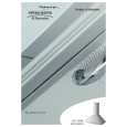
1. Tape run rough adjustment 1 Remove the cassette housing control assembly. 2 After shortcircuiting TP803 and TP802 provided at operation PWB, plug in the power cord. 3 Check and adjust the position of the tension pole. (See 4-12.) 4 Check and adjust the video search rewind back tension. (See 4-10.) 5 Connect the oscilloscope to the test point for PB CHROMA envelope output (TP201). Set the synchronism of the oscilloscope to EXT. The PB CHROMA signal is to be triggered by the head switching pulse (TP202). 6 Set the alignment tape (VROATSV) to play. (Put a 500g weight on the cassette tape to prevent lift of cassette tape.)
Guide roller
Notes: 1. Previously set the tracking control in the center position, and adjust the envelop waveform to maximum with X value adjustment nut. Thereby the tape run rough adjustment is facilitated. 2. Especially the outlet side envelope waveform must have higher flatness.
Cassette Tape
500g
Weight of 500g
Figure 4-32. 2. Adjustment of A/C head height and azimuth 1 Perform the initial setting of A/C head position by the method stated in "4-15 Replacement 3". 2 Connect the oscilloscope to the audio output terminal. 3 Using the alignment tape in which 1 kHz linear audio signal has been recorded, adjust the height screw so as to get max audio output. 4 Using the alignment tape in which 7 kHz linear audio signal has been recorded, adjust the azimuth screw so as to get max audio output. 5 The adjustment of 3 and 4 twice or three times repeat, and finally adjust 4.
Figure 4-31. 7 Press the tracking button (+), (�) and change the envelope waveform from max to min and from min to max. At this time make sure that the envelope waveform changes nearly parallel. 8 Unless the envelope waveform changes nearly parallel, adjust the height of supply side and takeup side guide roller so that the envelope waveform changes nearly parallel. (For envelop adjustment procedure refer to Figure 4-35.) 9 Turn the tilt screw to remove the tape crease at the fixing guide flange. Playback the tape and check for tape crease at the fixing guide flange. (1) If there is no tape crease Turn the tilt screw clockwise so that tape crease appears once at the flange, and then return the tilt screw so that the crease disappears. (2) If there is tape crease Turn counterclockwise the tilt screw so that the tape crease disappears. (Reference) If the tilt screw is turned clockwise crease appears at the lower flange.
For X value adjustment Adjust the X value, turning the gear-type screwdriver.
Figure 4-33. 3. Tape run adjustment 1 Connect the oscilloscope to PB CHROMA envelope output test point, set oscilloscope sync to EXT, trigger-input the PB CHROMA signal (head switching pulse). 2 Rough adjustment of X value Tentatively fix A/C head arm screws 1 and 2 by the method described in 4-15 "Replacement 3". Playback the alignment tape (VROATSV) and shortcircuit TP801 and TP802. As a result the autotracking is automatically cancelled, so that the X value adjustment mode is set. Move the A/C head with the X value adjustment gear driver (JiGDRiVER-6) by the method shown in Figure 4-33, and adjust the A/C head so as to get the maximum envelope waveform. (Note: When the A/C head is adjusted, adjust so that the maximum envelop waveform is obtained nearest the position of initial setting made in 4-15.)
22
|
|
|
> |
|