|
|
|
Categories
|
|
Information
|
|
Featured Product
|
|
|
 |
|
|
There are currently no product reviews.
 ;
Great and quick support. The maual was exactly what I was looking for and my problem
solved. Many thanks.
;
Very good service Within one day i received a pdf of the users manual and electric circuits so I was able to measure the different voltages in the printed circuit and find out the fault Payment was also reliable and easy.Without the manual i could not have repaired.So thanks to "Search for a manual"
 ;
you are doing great job guys.....my father ask me to find out the schematics of Sony KV25R1D to sort out the problem ..(he was electrical technician, and excperianced with TV and simillar stuff). finally he found the cause and change all necessary parts....now he has got working old dog..and is very happy!!... thank you all.. NB..he also saved the repair cost.
;
Perfect. Received my manual within 24 hours. Clear scan of the manual I needed. No problem.
;
Item as described, very well detailed manual with complete schematics. I've received the download information shortly after payment, very good support.
XL-30H/30W
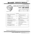
� HF error.
Is output (tracking error signal) obtained at the pins 46 (TEI) and 47 (TEZI) of IC802 the CD TEST MODE "STEP 4" is changed to "STEP 5"? Yes
test mode "step 4" test mode "step 5"
No
Is output obtained at the pins 2 and 5 of BI802/CNS802 No
Optical pickup failure.
Yes Check the periphery of IC801. Check the PWB pattern between pin 12. (TEO) of IC801 and pins 46 and 47 of IC802. Is it normal ? Yes Check the PWB pattern between pin 50 (TEO) of IC802 and pin 18 of IC804. Check the periphery of IC804 and BI801/CNS801. If OK. Optical pickup failure. IC801 is faulty. No
TEI TEZI
Is output (HF signal) obtained at the pin 38 (RFI) of IC802 when the CD TEST MODE "STEP 4" is changed to "STEP 5"? Yes
test mode "step 4" test mode "step 5"
No
Is output obtained at the pins 1 and 3, 4 of BI802/CNS802. No Yes Check the periphery of IC801.
Optical pickup failure.
RFI
Check the PWB pattern between pin 19 (RFGO) of IC801 and pins 38 (RFI) of IC802. If OK. IC801 is faulty
Is output (HF signal) obtained at the pins 41 (RFZI) and 42 (RFRP) of IC802 when the CD TEST MODE "STEP 4" is changed to "STEP 5"? Yes
RFZI RFRP test mode "step 4" test mode "step 5"
No
Check the periphery of IC801. Check the PWB pattern between pin17 (RFRP) of IC801 and pins 41 (RFZI) and 42 (RFRP) of IC802. If OK. IC801 is faulty.
Is the following wave output to the pin 55 (DMO) of IC802 when the CD TEST MODE "STEP 4" or "STEP 5"? Yes
DMO test mode "step 4" test mode "step 5"
No
Check the periphery pins 28~32 of IC802. If OK. IC802 failure.
Normal.
� No sound.
No sound from both L and R-ch? No Yes Check the interval between the pins 82 or 85 of IC802 and the pins 1 or 3 IC601.
Is +4.5V applied to pin 83 (DVDD) of IC802? Yes No
Check the PWB pattern between R819 and Q861.
Is signal of pins 82 and 85 of IC802 output? Yes The main PWB is faulty. No
Check the peripheral parts of IC802. If OK, IC802 is faulty.
� 42 �
|
|
|
> |
|