|
|
|
Categories
|
|
Information
|
|
Featured Product
|
|
|
 |
|
|
There are currently no product reviews.
 ;
Print was clear and easy to read. Thank you Joe joeoldaudio
;
Very great deal. In a few minutes a have the manual, that I needed. Thanl you very much
;
Manual was complete. Received it quickly. No problems
;
Product was very good. Received quickly and complete
 ;
The Sony AV-3600 service manual was what I needed for the repair of this unit
Thanks for the good service
Dave
XL-MP150H/MP150E
2. CD-MECHANISMUS
Führen Sie zum Ausbau des CD-Mechanismus die Schritte 1 bis 3, 14, 15 des Demontagevorgangs aus (siehe Seiten 3-3, 3-4).
Sicherungsscheibe (A3) x1 Optischer Abnehmer CDMechanismus (A1) x2 ø2.6 x5mm
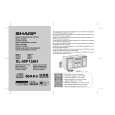
2.1. Optischen Abnehmer ausbauen (siehe Abb. 1)
1. Die beiden Schrauben (A1) lösen und die Welle (A2) abnehmen. 2. Sicherungsring (A3) und Zahnrad (A4) entfernen. 3. Optischen Abnehmer abnehmen. HINWEIS:U m w ickeln S ie nach d em E ntfernen des A nschlusse s für de n o ptischen A b nehm er da s vo rd ere E nde des A nsch lusses m it leitfähiger A lu m in ium folie, um d en o ptischen A bn ehm er vo r e lektrostatische r A ufladu ng zu schützen.
2.2. CD herausnehmen (siehe Abb. 2~6)
1. Wenn sich die CD in der Wiedergabeposition befindet, drehen Sie das in Abb. 2 dargestellte Untersetzungszahnrad C, bis sich das CD-Fach in der Position �STOCK� befindet. Drehen Sie es dann weiter, um das CD-Fach (Abb. 6) auszufahren, so dass die CD aus dem Fach genommen werden kann. 2. Wenn sich der CD-Mechanismus beispielsweise in der Wiedergabeposition für Fach Nr. 1 befindet und die in Fach Nr. 3 befindliche CD entnommen werden soll, gehen Sie wie folgt vor: Wenn sich die Senk-/Hebeplatte in der Position für Fach Nr. 1 befindet, drehen Sie das Untersetzungszahnrad C im Uhrzeigersinn, bis sich das CD-Fach in der Position �STOCK� befindet. Drehen Sie das Untersetzungszahnrad D im Uhrzeigersinn (Abb. 3), um den CD-Mechanismus in die Position für Fach Nr. 3 zu bewegen. Dies kann anhand der Position der Senk-/Hebeplattebasis zur auf dem Hauptgehäuse gezeigten Markierung überprüft werden (s. Abb. 4). � Der Wechsler ist normalerweise durch die obere Platte abgedeckt. Zur besseren Veranschaulichung ist die obere Platte nicht dargestellt. (Abb. 5, 6)
CD Disc-Fach Führungsfach
Antrieb (A4) x1
Welle (A2) x1
Abb. 1
Untersetzungsrad C
Vorne
Hinten
Abb. 2
Untersetzungsrad D
Auf
Ab
Abb. 3
CD in Position 'PLAY'. CD Disc
Senk-/Hebeplatte
CD in Position 'STOCK'.
Abb. 5
CD
Markierung 1 Markierung 3 Markierung 5 (DISC 1) (DISC 3) (DISC 5) Markierung 2 Markierung 4 (DISC 2) (DISC 4)
CD aus Fach nehmen. Fach öffnen
Abb. 4 Abb. 6
3�2
|
|
|
> |
|