|
|
|
Categories
|
|
Information
|
|
Featured Product
|
|
|
 |
|
|
There are currently no product reviews.
 ;
It was very usefull, it is clear the quality is super, the price I paid is very afordable.
Generally speaking Iam very happy with this company.
;
The manual was exactly what I needed, Good quality scans too. superb.
;
I am so happy found this site as it consists of so many Manuls and easy to aquire. This onei s exactly what I wanted and much more as it has info on not only how to use the tuner but how to repair it as well. I will come here 1st before purchasing else where! Thanks owner-manual.com!
;
Top class product, I printed it out on A3 paper and it is clear and very easy to follow.
Cheaper than buying a new radio!
;
is part of the manual is very useful for repairing
Here are circuit diagrams
if there is damage, I recommend using this part of the
a complete list of circuit boards and components
XR-A6800, XR-A4800
6. ADJUSTMENT
6.1 TUNER SECTION
FM Tuner Section
� Set the mode selector to FM BAND. � Connect the wiring as shown in Fig. 1. Step No. Adjustment Title FM SG (1kHz, ± 75kHz dev.) Frequency Level (MHz) (dBµV)
106 98 (ON STEREO) 98 0 to 30
Reception Frequency Display
106MHz
Adjustment Location
L6104 L6105 L6102 T6101 T6101 VR6201
Specifications
1
Front End Sensitivity Stereo Distortion TUNED IND. Lighting Level
Adjust so that the DC voltage between the IC6201 - pin 20 and GND becomes at maximum level. Minimize the distortion with 1/8 rotation of the core. Adjust so that the indicator of TUNED IND. starts to light up.
2 3
80 18 ± 2
98MHz 98MHz
Note: Before adjusting, make sure there is no gap between L6101 and L6102 as well as between L6103 and L6104. If there is a gap between them, bring them into contact with each other first, and then make adjustments.
AM Tuner Section
� Set the mode selector to AM BAND. � Connect the wiring as shown in Fig. 1. Step No. Adjustment Title
Front End Sensitivity
AM SG (400Hz, 30% Mod.) Frequency Level (kHz) (dBµV/m)
999 (�1) 35 to 45
Reception Frequency Display
999kHz (�1)
Adjustment Location
Specifications
Adjust so that the DC voltage between the IC6201 - pin 20 and GND becomes at maximum level.
1
T6201
Note (�1) : For the area using 10kHz step, frequency should be 1000kHz. 60cm Loop antenna
AM SG
Center
Center
AM antenna terminal DC Voltmeter
MPX SG
FM SG FM75� antenna terminal
PRODUCT
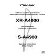
Fig.1 AM and FM Adjustment Wiring Diagram
FM/AM TUNER MODULE
AM antenna terminal T6201 AXX7042 YELLOW FM antenna terminal BLACK L6105 T6101 L6102 L6103 L6104
IC6201 Pin 20
VR6201
L6101
Fig.2 Adjustment Point
53
|
|
|
> |
|