|
|
|
Categories
|
|
Information
|
|
Featured Product
|
|
|
 |
|
|
There are currently no product reviews.
 ;
Good quality, all schematics of few of models. There is also short form of user manual and regulation manual.
;
Perfect copy of the service manual. you can enlarge every page, and it comes up
with all details.
;
It´s very very nice manual with all, what i need. Original in good quality. Very fast business. Very much thanks...
;
Purchased the manual that I was looking for at a great price and could download it easily.. Great service experience and for future purchases I plan to use the site.
Thank you very much
;
Exactly what was needed to assess the product - excellent value and great service
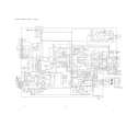
ADJUSTMENT -2
<DECK: U, LH, HR, HE, EZ, K>
~
DECK C.B DECK R / P / E HEAD
L
<DECK
DC= ��s!!!!!
A
1
6 2
REV
02
FWD
PRACTICAL SERVICE FIGURE
SECTION> <DECK SECTION> 3000Hz + 45Hz Less than O.14% (R.M.S) 270- 330g (FWD, REV) 30- 55g-cm @WD, REV) 75- 180g-cm 2- 7g-cm (FWD, REV) Less than 2.0% (PB, AC) Less than 3.0% (REC/PB, AC) Less than 120mV (PB, AC) Less than 120mV (REC/PB, AC) More than 40dB (PB, AC) More then 38dB (REC/PB, AC) More than 55dB (at 125Hz) 63Hz �2/-l0dB - 10kHz +2/�7dB(PB) 125Hz +1/-9dB - iOkHz +4/�7dB (REC/PB) TTA-21O TTA�31O TT�A-320 TTA-602 1. Tape Speed Adjustment Settings : q Test tape : TTA�1OO Test point: SPK OUT Adjustment location: SFR 1 Method: Play back the test tape and adjust SFR1 for q 3000Hz ~ 45Hz (FWD) and MD PLAY speed ~ 45 Hz (REV).
q q
Tape speed : Wow & flutter: Pinch roller pressure : Take-up torque : F.F & REW torque: Back tension: Distortion : Noise level : S/N ratio: Erasing ratio : Frequency response:
2. Head Azimuth Adjustment Settings : Test tape : TTA�300 Test point: SPK OUT Adjustment location : Head azimuth adjustment screw Method : Play back the 10kHz signal of the test tape and adjust screw so that the output becomes maximum. Next, perform on each FWD PLAY and REV PLAY mode.
q q q
Test tape :
3. PB Frequency Response Check Settings : Test tape : TTA-320 Test point: SPK OUT Method: Play back the 63Hz, 315Hz and 10kHz signals of the test tape and check that the 63Hz signal with respect to that of the 315Hz signal is �2dB to �lOdB and the 10kHz signal with respect to that of the 315Hz signal is +2dB to -7dB.
q q
4, REC/PB Frequency Response Check Settings : Test tape : TTA�602 Test point: SPK OUT Method: Input a �8dB signal to the AUX terminal. Record the 125Hz and 10kHz signals on the test tape and play back them. Check that the difference between the record level and the play back level at 125Hz signal is ldB to -9dB and at 10kHz signal is +4dB to -7dB.
q q
78
 $4.99 XRM25 AIWA
Owner's Manual Complete owner's manual in digital format. The manual will be available for download as PDF file aft…
|
|
|
> |
|