|
|
|
Categories
|
|
Information
|
|
Featured Product
|
|
|
 |
|
- SERVICING NOTES
- GENERAL
- Location of Controls (XR - M500R)
- Setting the Clock
- Changing the Sound and Display Setting
- Locations of Controls (XR - M550)
- Setting the Clock
- Changing the Sound and Display Setting
- Installation (XR - M500R)
- Installation (XR - M550)
- Connections (XR - M500R)
- Connections (XR - M550)
- DISASSEMBLY
- ASSEMBLY
- MECHANICAL ADJUSTMENTS
- ELECTRICAL ADJUSTMENTS
- Tape Deck Section
- Tuner Section
- DIAGRAMS
- Block Diagram - TUNER/TAPE Section
- Block Diagram - MAIN Section
- Block Diagram - DISPLAY/BUS CONTROL Section
- Block Diagram - POWER SUPPLY Section
- Note for Printed Wiring Boards and Schematic Diagrams
- Printed Wiring Board - MAIN Board (Component Side)
- Printed Wiring Board - MAIN Board (Conductor Side)
- Schematic Diagram - MAIN Board (1/4)
- Schematic Diagram - MAIN Board (2/4)
- Schematic Diagram - MAIN Board (3/4)
- Schematic Diagram - MAIN Board (4/4)
- Printed Wiring Board - SUB Board
- Schematic Diagram - SUB Board
- Printed Wiring Board - DISPLAY Board
- Schematic Diagram - DISPLAY Board
- IC Pin Function Description
- EXPLODED VIEWS
- ELECTRICAL PARTS LIST
- NEW/FORMER TYPE DISCRIMINATION
- DIAGRAMS
- Note for Printed Wiring Boards and Schematic Diagrams
- Printed Wiring Boards - MAIN Board (Component Side) - (XR - M550 Only)
- Printed Wiring Boards - MAIN Board (Conductor Side) - (XR - M550 Only)
- Schematic Diagram - MAIN Board (1/4) - (XR - M550 Only)
- Schematic Diagram - MAIN Board (2/4) - (XR - M550 Only)
- Schematic Diagram - MAIN Board (3/4) - (XR - M550 Only)
- Schematic Diagram - MAIN Board (4/4) - (XR - M550 Only)
- Printed Wiring Boards - SUB Board - (XR - M550 Only)
- Schematic Diagram - SUB Board - (XR - M550 Only)
- Printed Wiring Boards - DISPLAY Board
- Schematic Diagram - DISPLAY Board
- EXPLODED VIEWS
- ELECTRICAL PARTS LIST
There are currently no product reviews.
 ;
Thank you very much. the Instruction corresponds to my expectations. Sent it in time. I don't regret that paid money.
;
Good quality. Quick service. I recommend to everyone.
;
Very good quality scan of the document. I am very pleased with what I got.
;
PDF Contains
Technical Data, Mechanical data, Detailed Circuit diagram with components value, PCB layout. Actual PCBs Print. Component List, Spare parts code list and Input output detail. It cover LBB1211, LBB1212, LBB1213, LBB1216, LBB1217.
It is the actual Service Manual for SQ10
;
very good manual with clear electrical schemes. Very helpful to find wat was wrong inside my microwave.
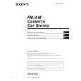
SECTION 4 ASSEMBLY
Note: Follow the assembly procedure in the numerical order given.
4-1. FRONT PANEL MACHINERY MOTOR BLOCK ASS�Y
2 stop ring 1 cam (L) hole 6 washer (M) 7 bracket (motor) ass'y
5 gear (C)
switch
4 gear (B)
6 washer (M) Set bracket (motor) ass�y to be at the position in the figure.
3 gear (A) concave portion
Note: When installing cam (L), adjust the hole and concave portion.
8 two screws (PTT2.6 � 6)
8 screw (B2.6 � 6)
CAM (R) ASS�Y
2 stop ring 1 cam (R) hole
concave portion
Note: When installing cam (R), adjust the hole and concave portion.
19
 $4.99 XR-M550 SONY
Owner's Manual Complete owner's manual in digital format. The manual will be available for download as PDF file aft…
|
|
|
> |
|