|
|
|
Categories
|
|
Information
|
|
Featured Product
|
|
|
 |
|
|
There are currently no product reviews.
 ;
VERY GOOD SERVICE.FAST ANS VERY HONEST PRICE .RHAANK HERNAN
 ;
Thanks to this service manual I repaired my old camcorder! The manual perfectly explains how to disassemble the camcorder step by step.
;
This manual is very useful because it presents the technical specifications of the cd player, including the manufacturer of the reader, this helps if you need to replace it. It also displays the settings and layout of the circuit.
;
Manual was a good representation of service infomation for the EWV404. It worked well for my repair.
;
Great quality copy, right what I was looking for, all I need to fix my radio.
Thanks
5. DISASSEBLY AND ASSEMBLY PROCEDURES
For disassembly of the ZQ-800, perform the following procedures. For assembly, reverse the disassembly procedures.
2 5 8 8 6
A
1 13
16 15 14 4 14 9 7 3 3
A
12 12 10 11
12
5-1. LOWER CABINET 4 AND UPPER CABINET 5 DISASSEMBLY
1. Remove the stylus 1. 2. Slide the battery replacement switch to the �REPLACE BATTERIES� side, and remove the battery compartment lid. 3. Remove two alkaline batteries. 4. Remove two screws 2. Note: Do not apply an excessive force when removing the screws. 5. Remove two screws 3. Note: Do not apply an excessive force when removing the screws. 6. Separate the lower cabinet 4 from the upper cabinet 5. [Note for separating the lower cabinet] � First, disengage all the pawls around the cabinet. � The Main PWB unit 6 and the LCD unit 7 are connected with FPC. When separating the lower cabinet 4, remove the lower cabinet 4 from the jack cover side of the PC-LINK so that an excessive load may not be applied to the FPC connector of the Main PCB unit 6 and the FPC solder section of the LCD unit 7. 7. Remove the FPC from the FPC connector of the Main PWB unit 6. [Note for the FPC connector] � When handling the FPC connector, be careful not to apply a reverse load to the connector lock section.
About 120 C FPC insertion side FPC connector PWB
Release the lock smoothly
Lock plate FPC insertion side
Do not press the Lock plate unnecessarily in the reverse direction. FPC connector PWB
ZQ-800 DISASSEBLY AND ASSEMBLY PROCEDURES
� 13 �
 $4.99 ZQ-800 SHARP
Owner's Manual Complete owner's manual in digital format. The manual will be available for download as PDF file aft… 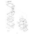 $4.99 ZQ-800 SHARP
Parts Catalog Parts Catalog only. It's available in PDF format. Useful, if Your equipment is broken and You need t…
|
|
|
> |
|