|
|
|
Categories
|
|
Information
|
|
Featured Product
|
|
|
 |
|
|
There are currently no product reviews.
 ;
Great quality complete service manual!!! complete parts list and drawings
;
Again a great job. I never been disilluted from them! Clear scheme, complete and very good for repairing!
;
Great manual just what I needed, great service as always, thanks.
;
Great quality complete service manual! complete parts list and drawings. Thanks!
;
Great quality complete service manual! complete parts list and drawings. Thanks!
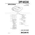
SECTION 3 MECHANICAL ADJUSTMENTS
Replacing the Thermal Head
1) Before replacing the head, print the stair-step pattern with the old head (faulty head).
Note 1: Only when the head is not entirely damaged with black or white lines. Note 2: To reproduce the stair-step pattern, refer to �Adjusting Method 1� in �4. Electrical Adjustments�.
6) Remove the two screws 8 (PSW2.6 � 8) and remove the thermal head 9 from the heat sink 0. (Refer to Fig. 2)
Note: Do not remove the screw !� fixing the heat sink 0 and head arm !¡.
7) Replace the thermal head 9.
Note: Make sure that the silicon grease (white) does not stick onto the printing screen of the thermal head. If it does, remove with alcohol.
2) Remove the upper cabinet. (Refer to �2. Disassembly�.) 3) Remove the flat cables 1 (POHE13) and 2 (ADHE13) from the thermal head. (Refer to Fig. 1) 4) Remove the two screws 3 (BVTT2.6 � 6) and remove the harnesses 4 and fan holder 5. (Refer to Fig. 1) 5) Remove screw 6, (PS2.6 � 4) and remove the ribbon guide 7. (Refer to Fig. 2)
8) Assemble in the reverse order of steps 2) to 6). 9) Perform �Head Voltage Adjustment� of �4. Electrical Adjustments� (Page 4-3).
4 harness
3 two screws (BVTT2.6 � 6)
7 ribbon guide
6 screw (PS2.6 � 4)
4 harness
two screws !� Note: Do not remove the screw.
8 two screws (PSW2.6 � 8)
5 fan holder 1 flat cable (POHE13)
0 heat sink
2 flat cable (ADHE13)
9 thermal head
!¡ head arm
Fig. 2
Fig. 1
3-1 E
|
|
|
> |
|